

- Operating Voltage: 5V
- Internal Potentiometer value: 10k
- 2.54mm pin interface leads
- Dimensions: 1.57 in x 1.02 in x 1.26 in (4.0 cm x 2.6 cm x 3.2 cm)
- Operating temperature: 0 to 70 °C
- Weight (kg): 0.015
Dual-axis XY Joystick Module Higher Quality PS2 Joystick Control Lever Sensor KY-023 5Pin For Arduino
Brand: No Brand
Free Shipping
৳ 179৳ 300-40%
In Stock
SKU: CU-2196954-3652848
Category : Electrical Circuitry Parts
Specifications
Product Details
Description: Joystick Module For Arduino
Analog joystick-like devices used for example Controllers PlayStation second detection directions of traffic is carried by two potentiometers – one (4.7 k Ω ) on each axle. The device also has a button activated by pressing the knob . To operate the device, all you need is a microcontroller with an analog-to-digital converter (analog input in Arduino ). The location information of the knob is transmitted through an analog signal, in which the voltage corresponds to the given position. Each axis has a separate analogue output. The state of the button is detected by a digital output which, when switched on, becomes low.
1. Input voltage range: DC 3.3V to 5V
2. Output signal: the module has two-way analog output and a digital output interface, the output value corresponding to (X, Y) bi-axial offset, the type of analog; keys that the user press, the Z axis is a push switch read as digital input.
3.Arduinocontroller can be programmed, the sensor expansion board plug, complete with creative remote interactive works.
4. Crossjoystickis a bi-directional 10K resistor, with the rocker in different directions, the resistance should be changed by moving the lever. This module uses 5V power supply, the original state of X, Y read voltage of 2.5V or so, when pressed with the arrow direction, the read voltage value increases with the maximum to 5V, voltage decreases while move lever in opposite direction, The minimum is 0V.
You have to use 2 analog inputs of MCU to read (X Y) the analog output of this module, the switch is a button which you may use with a digital input pin of your Micro Controller eg.Arduino,Raspberry Pi,Orange Pi,NodeMCU,ESP32,ARMAVR development boards.
Features:
- Two independent Potentiometer: one for each axis ( X and Y)
- Auto return to center position
- Low weight
- Cup-type Knob
- Compatible to interface with Arduino or with most microcontroller
- Easy breadboard connection
- Two independent 10K potentiometers with common ground
- Spring auto-return to center
- Comfortable cup-type knob
Technical Specifications:
- Operating Voltage: 5V
- Internal Potentiometer value: 10k
- 2.54mm pin interface leads
- Dimensions: 1.57 in x 1.02 in x 1.26 in (4.0 cm x 2.6 cm x 3.2 cm)
- Operating temperature: 0 to 70 °C
Connection:
Using the joystick connection plate, it boils down to connecting the following pins:
- VCC– Supply voltage (5 V).
- GND– System weight.
- VRx– Analog output for the vertical axis (in the middle position, the value equal to half the voltage supply VCC / 2).
- VRy– Analog output for the horizontal axis (in the middle position, the value equal to half the voltage supply VCC / 2).
- SW– The digital signal of the button, when switched on, reaches the GND value, switched off – it is in theposition– so you should add the pull-up resistor to the power supply
Pin Configuration:
Internal Structure
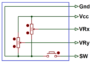
The below image is theinternal diagram of a Joystick Module. It consists of twoPotentiometer, each for one axis (X and Y). Both 10k potentiometer are independent to move in their particular direction. SW (Switch) pin is connected to a push button internally.
Where Joysticks Are Used?
When we listen the word “Joystick” we think of Game controllers. If we talk about Electronics there are many useful application of Joystick. These type of module are mostly used inArduinobased DIY projects and Robot Control. As we know, the module gives analog output so it can be used for feeding the analog input based on direction or movement. It can also be connected to a movable camera to control its movement.
How to Use Joystick?
We can use a Joystick Module with Arduino, Raspberry Pi and any other Micro-controllers. We just have to connect the axis Pins VRx and VRy to the ADC Pins of the micro-controller. If you want to use the switch then connect it to the digital Pin of the Micro-controller. Follow the below block diagram to connect Joystick Module with Microcontroller.
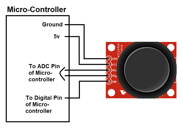
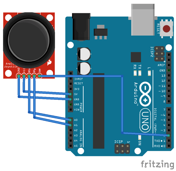
As used in many projects, the interfacing diagram ofJoystick Module with the Arduinois given below. It helps you to connect the joystick Module with Arduino and get the analog output based on the direction of movement of Joystick Knob.
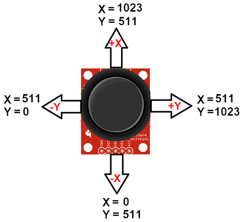
After Interfacing Joystick Module with the Arduino, we will get the analog output. The output range is fixed for each direction. The below image shows, the value of analog output for X and Y axis based on the movement of Joystick Module in all four directions (+X, -X, +Y, -Y). You will also get some analog value when moving the knob diagonally.
Application:
- Camera Pan/Tilt Control
- Game Input/Control
- Robot Control
- Analog Input of Parameters
- Widely use in DIY projects
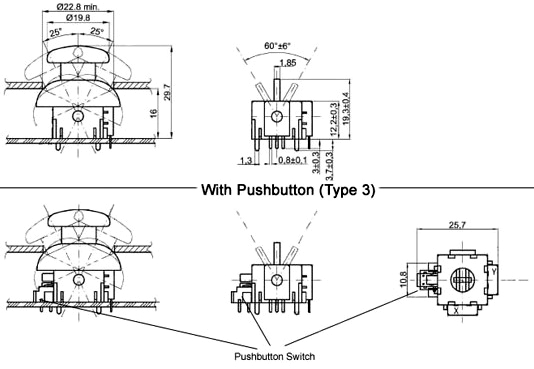
2D-model
Documents:
Specifications:
- Dimensions (cm): 11 x 8 x 2
- Weight (kg): 0.015
Package Included:
- 1 x Joystick Module For Arduino
Delivery
Inside Dhaka
Standard delivery
Free
Service
7 Days Returns
Change of mind is not applicable as a Return Reason. To learn more, please check Return Policy
No Warranty
Ratings & Reviews of Dual-axis XY Joystick Module Higher Quality PS2 Joystick Control Lever Sensor KY-023 5Pin For Arduino

Rahman Regnum Centre, Level-6, 191/1, Tejgaon C/A, Dhaka-1208, Bangladesh

9 am - 9 pm (Everyday)

Follow us on
Customer Care
Payment Methods






© Copyright 2026 Cartup All Rights are Reserved.

